(China (Mainland))

Product Summary
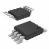
| Description | IC CTRLR RF POWER SINGLE 8MSOP | RF type | Mobile phone, GSM, PCS, wireless modem, TDMA |
|---|---|---|---|
| Hz | 850MHz ~ 2GHz | Features | Single Tap |
| Encapsulation/shell | 8-TSSOP,8-MSOP(0.118",3.00mm wide) | Supplier equipment packaging | 8-MSOP |
| pack | Fitting |
Parametrics
LTC1757A-1/LTC1757A-2
The l denotes specifications which apply over the full operating
temperature range, otherwise specifications are at TA = 25°C. VIN = 3.6V, SHDN = TXEN = HI, unless otherwise noted.
PARAMETER CONDITIONS MIN TYP MAX UNITS
SHDN, TXEN, BSEL Input Current SHDN, TXEN or BSEL = 3.6V l 10 30 50 μA
PCTL Input Voltage Control Range VIN = 2.7V to 4.7V, RLOAD = 400Ω l 0 2 V
PCTL Input Voltage Range VIN = 3V, RLOAD = 400Ω (Note 8) l 2.4 V
PCTL Input Resistance SHDN = LO, TXEN = LO l 50 100 150 kΩ
PCTL Input Filter 1.25 MHz
Autozero Range VIN = 2.7V, RLOAD = 400Ω (Note 4) l 400 mV
Autozero Settling Time (tS) Shutdown to Enable (Autozero), VIN = 2.7V (Note 11) l 50 μs
RF Input Frequency Range (Note 6) l 850 2000 MHz
RF Input Power Range 900MHz (Note 6) – 24 16 dBm
1800MHz (Note 6) –22 16 dBm
RF DC Input Resistance Referenced to VIN, SHDN = LO, TXEN = LO l 100 175 250 Ω
VIN Overvoltage Range VPCA/B < 0.5V, RLOAD = 400Ω l 4.8 5.0 5.4 V
BSEL Timing t1, Setup Time Prior to TXEN Asserted High 200 ns
t2
, Hold Time After TXEN is Asserted Low 200 ns
Note 1: Absolute Maximum Ratings are those values beyond which the life of
a device may be impaired.
Note 2: The LTC1757A-1 and LTC1757A-2 are guaranteed to meet performance
specifications from 0°C to 70°C. Specifications over the –30°C to 85°C
operating temperature range are assured by design, characterization and
correlation with statistical process controls.
Note 3: Slew rate is measured open loop. The slew time at VPCA or VPCB is
measured between 1V and 2V.
Note 4: Maximum DAC zero-scale offset voltage that can be applied to PCTL.
Note 5: This is the time from TXEN rising edge 50% switch point to
VPCA/B = 1V.
Note 6: Guaranteed by design. This parameter is not production tested.
Note 7: For VIN voltages greater than 4.7V, VPCA/VPCB are set low by the
overvoltage shutdown.
Note 8: Includes maximum DAC offset voltage and maximum control voltage.
Note 9: Bandwidth is calculated using the 10% to 90% rise time equation:
BW = 0.35/rise time
Note 10: Measured 1μs after TXEN = HI.
Note 11: 50% switch point, SHDN HI = VIN, TXEN HI = VIN
Features
LTC1757A-1/LTC1757A-2
The l denotes specifications which apply over the full operating
temperature range, otherwise specifications are at TA = 25°C. VIN = 3.6V, SHDN = TXEN = HI, unless otherwise noted.
PARAMETER CONDITIONS MIN TYP MAX UNITS
SHDN, TXEN, BSEL Input Current SHDN, TXEN or BSEL = 3.6V l 10 30 50 μA
PCTL Input Voltage Control Range VIN = 2.7V to 4.7V, RLOAD = 400Ω l 0 2 V
PCTL Input Voltage Range VIN = 3V, RLOAD = 400Ω (Note 8) l 2.4 V
PCTL Input Resistance SHDN = LO, TXEN = LO l 50 100 150 kΩ
PCTL Input Filter 1.25 MHz
Autozero Range VIN = 2.7V, RLOAD = 400Ω (Note 4) l 400 mV
Autozero Settling Time (tS) Shutdown to Enable (Autozero), VIN = 2.7V (Note 11) l 50 μs
RF Input Frequency Range (Note 6) l 850 2000 MHz
RF Input Power Range 900MHz (Note 6) – 24 16 dBm
1800MHz (Note 6) –22 16 dBm
RF DC Input Resistance Referenced to VIN, SHDN = LO, TXEN = LO l 100 175 250 Ω
VIN Overvoltage Range VPCA/B < 0.5V, RLOAD = 400Ω l 4.8 5.0 5.4 V
BSEL Timing t1, Setup Time Prior to TXEN Asserted High 200 ns
t2
, Hold Time After TXEN is Asserted Low 200 ns
Note 1: Absolute Maximum Ratings are those values beyond which the life of
a device may be impaired.
Note 2: The LTC1757A-1 and LTC1757A-2 are guaranteed to meet performance
specifications from 0°C to 70°C. Specifications over the –30°C to 85°C
operating temperature range are assured by design, characterization and
correlation with statistical process controls.
Note 3: Slew rate is measured open loop. The slew time at VPCA or VPCB is
measured between 1V and 2V.
Note 4: Maximum DAC zero-scale offset voltage that can be applied to PCTL.
Note 5: This is the time from TXEN rising edge 50% switch point to
VPCA/B = 1V.
Note 6: Guaranteed by design. This parameter is not production tested.
Note 7: For VIN voltages greater than 4.7V, VPCA/VPCB are set low by the
overvoltage shutdown.
Note 8: Includes maximum DAC offset voltage and maximum control voltage.
Note 9: Bandwidth is calculated using the 10% to 90% rise time equation:
BW = 0.35/rise time
Note 10: Measured 1μs after TXEN = HI.
Note 11: 50% switch point, SHDN HI = VIN, TXEN HI = VIN
Diagrams

| Image | Part No | Mfg | Description |  |
Pricing (USD) |
Quantity | ||||||
|---|---|---|---|---|---|---|---|---|---|---|---|---|
 |
 LTC1757A-1 |
Other |
|
Data Sheet |
Negotiable |
|
||||||
 |
LTC1757A-1EMS8#PBF |
|
IC CTRLR RF POWER SINGLE 8MSOP |
Data Sheet |
Negotiable |
|
||||||
|
LTC1757A-2 |
Other |
|
Data Sheet |
Negotiable |
|
||||||
 |
LTC1757A-2EMS |
|
IC CTRLR RF POWER DUAL 10MSOP |
Data Sheet |
|
|
||||||
|
LTC1757A-2EMS#TR |
|
IC CTRLR RF POWER DUAL 10MSOP |
Data Sheet |
|
|
||||||
|
LTC1757A-2EMS#TRPBF |
|
IC CTRLR RF POWER DUAL 10MSOP |
Data Sheet |
Negotiable |
|
||||||
|
LTC1757A-2EMS#PBF |
|
IC CTRLR RF POWER DUAL 10MSOP |
Data Sheet |
Negotiable |
|
||||||
|
LTC1757A-1EMS8#TRPBF |
|
IC CTRLR RF POWER SINGLE 8MSOP |
Data Sheet |
Negotiable |
|
||||||